The Trent Severn Waterway Lock # 21
How the Peterborough and Kirkfield Lift Locks work.
The Peterborough Lift Lock on The Trent Severn Waterway was opened
in July, 1904. It transfers boats, up and down in a single lift of
65 feet (19.8 m).
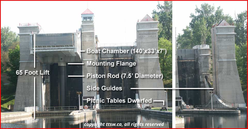
Needed Data (English Units of Measure):
- Boat chamber size: 140 ft by 33 ft by 7 ft deep (holds the boats)
- Piston Rod: 7.5 feet in Diameter (holds the chambers up and moves up and down)
- Lift: 65 ft (the distance the chamber is raised or lowered)
- Weight of water: 1 cubic foot of water weight 62.43 pounds (may be a fluid or a water soluble fluid mixed in)
- The Upper Chamber is filled with 7 feet of water depth and the Lower Chamber with 6 feet of depth.
- A boat displaces it's own weight in water, Principle of Flotation. The number, weight or size of boats in either chamber will not impact the operation.
- Path of Least Resistance is what moves the lower unit up and allows the upper unit to descend.
Assumptions:
- Piston Rod travel (65+65) = 130 feet (65 ft out of the cylinder and 65 ft into the cylinder).
- You need to keep some of the Piston Rod in the Cylinder at the top of the stroke plus some room at the bottom of the Cylinder to accommodate that.
- The side guides supports the Chambers from breaking free so the Piston Rods add an extra safety feature assisting the Side Guides to achieve that result.
- The bottom of the cylinder would require some extra footage so the Piston Rod at all times is well within the cylinder and not bottomed out.
- The overall height would be approximately that of
a 12 story building were it all above ground.
Calculations:
- Upper Chamber Water Fill: 140 x 33 x 7 = 32,340 Cubic Feet or 915.8 Cubic Meters
- Lower Chamber Water Fill: 140 x 33 x 6 = 27,720 Cubic Feet or 784.9 Cubic Meters
- Weight of the water (Upper Chamber): 32,340 x 62.43 = 2,018,986.2 pounds or 915,796.7 Kg
- Weight of the water (Lower Chamber): 27,720 x 62.43 = 1,730,559.6 pounds or 784,968.6 Kg
- 2,018,986.2 pounds = 901.3 imperial tones or 1,009.5 US tons or 915.8 metric tons
- Area of the Piston Rod =
 = 3.14 x 3.75 x 3.75 =
44.2 square feet (pi times radius squared)
= 3.14 x 3.75 x 3.75 =
44.2 square feet (pi times radius squared) - The Upper Chamber's Pressure is: 2,018,986.2/44.2 = 45,678 pounds per square foot or 317.21 PSI or 2,187.09 kPa
- The Lower Chamber's Pressure is: 1,730,559.6/44.2 = 39,152 pounds per square foot or 271.89 PSI or 1,874.62 kPa
- What this all boils down to is (317.21 psi - 271.89 psi) = 45.32 psi lifts the lower unit
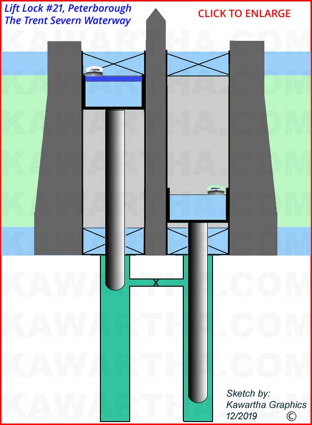
In the sketch, I have shown the piston rod as a half a sphere
at the bottom. This creates 2 times the surface area of a flat circle having
the same diameter.
The
water
pressure surrounding the rod, if in fact that is the actual design, will act
as a minor resistance to travel and the upward push happens on the sphere.
Area
of a Sphere is,  ,
four multiplied by pi and then multiplied by the radius squared, finally
divided by 2 because only half is used.
,
four multiplied by pi and then multiplied by the radius squared, finally
divided by 2 because only half is used.
Opening the valve between the two cylinders lets the heavier
boat chamber, which is at the top of its stroke, descend. That in turn, increases
the pressure
in both cylinders forcing the lighter boat chamber, which is at the bottom of
its stroke, up. Rapids and drops within the rivers are bypassed in order to
navigate between the previous and next lock. The principle is the same for the
other locks, which can vary from Conventional Locks, Flight Locks, Marine Railroads
or Lift Locks. The goal to go smoothly from points A to B is met.
Pressure attempts to push the water out of the cylinders
by finding the "Path of Least Resistance".
The cylinders are sealed so the water cannot escape and the system cannot
allow the pressure to exceed the Design Limit. Both are
resolved as the lighter chamber
moves up resulting in equalized pressure throughout. Opening the connecting
valve between the two cylinders allows the water and pressure to flow from
the unit
at the top of its stroke to the unit at the bottom. When the full stroke
is completed, the valve closed, the water level in the unit moving down will
have stopped one foot above the level of the Trent Canal and the unit moving
up will have stopped one foot below the level of the Trent Canal. Water is
then added or released, as needed, so the gates can open and boats can transfer
in our out starting the process over again. A very simple set of principles
used in an extreme situation due to the size and weight involved.
Many scenarios of worst case can be considered.
Short of a total traumatic failure in the structure the worst I can
think of happening
is that one of the stationary holding gates at the top fails and
opens, flooding the entire chamber beneath with more than the designed
foot
of extra water resulting in exceeding
system’s
Design Limit for pressure, breeching either cylinder
or, most likely the connecting pipe between the cylinders. That in
itself could create
a number of events to occur none with a happy ending..
Lock #21, Peterborough's Hydraulic Lift Lock, built
from 1896 to 1904. A magnificent achievement even by today's standards
and tools available.
Disclaimer: This document is theoretically correct
but the sizes may vary slightly in actuality, as the Government agencies
never
seem to publish data that is useful in this kind of document. It
may be out by inches or a foot but it is all we could find at the
time of creating the document. In industry I had a rule: "you
cannot be promoted till you can be replaced so pass on your knowledge,
correctly and faithfully, so others can follow you smoothly and with
minimal disruption."
Flight locks are locks joined together, like steps, to allow for
a higher lift, just like a Lift Lock but not as efficient.
The other Locks are simply two sets
of doors that open and close so when the chamber is
filled with water the upper doors open so vessels can
move in or out. Closed, to allow the water to be pumped
out
to the water level at the lower chamber, then those doors open
and the vessels
can move in or out.
Brief History of The Trent-Severn Waterway
The start to finish time line spans eighty-seven
years with the systems construction starting in 1833 at Bobcaygeon
and finishing in 1920 at Port Severn, three hundred and eighty-seven
kilometers from Lake Ontario.
The Navigation channel runs a depth
of six feet from start to finish. The locks vary in raising
the water level some exceptions are; flight locks, the Big
Chute Marine Railway with a lift of eighteen meters (58 feet),
the Kirkfield Lift Lock with an average lift of fifteen meters
(49 feet) and the Peterborough Lift Lock (finished in 1904)
with a lift of twenty meters (65 feet).
Peaking at Balsam Lake at 180 meters
(600 feet) above Lake Ontario and 80 meters (250 feet) above
Lake Huron’s, Georgian Bay.
Standard lock dimensions are one
hundred and twenty feet long by thirty-two feet wide. The three
exceptions are the lock 21, lock 44, the Big Chute Marine
Railway at one hundred feet long by twenty-four
feet wide and lock 21 is slightly larger, lock 45 at Port Severn
is only eight-four feet long and twenty-three feet wide setting
the
limit if you
wish
to traverse The Trent Severn Waterway from one end to the other.
Canadian News
National Post - Canada
Global News - Canada
CTV News - Canada
Toronto Star - Canada
The Rebel - Canada
The Correspondent - Canada/World
Vancouver Sun - Canada
Montreal Gazette - Canada
Conservative Party of Canada
Liberal Party of Canada
NDP Party of Canada
Green Party of Canada